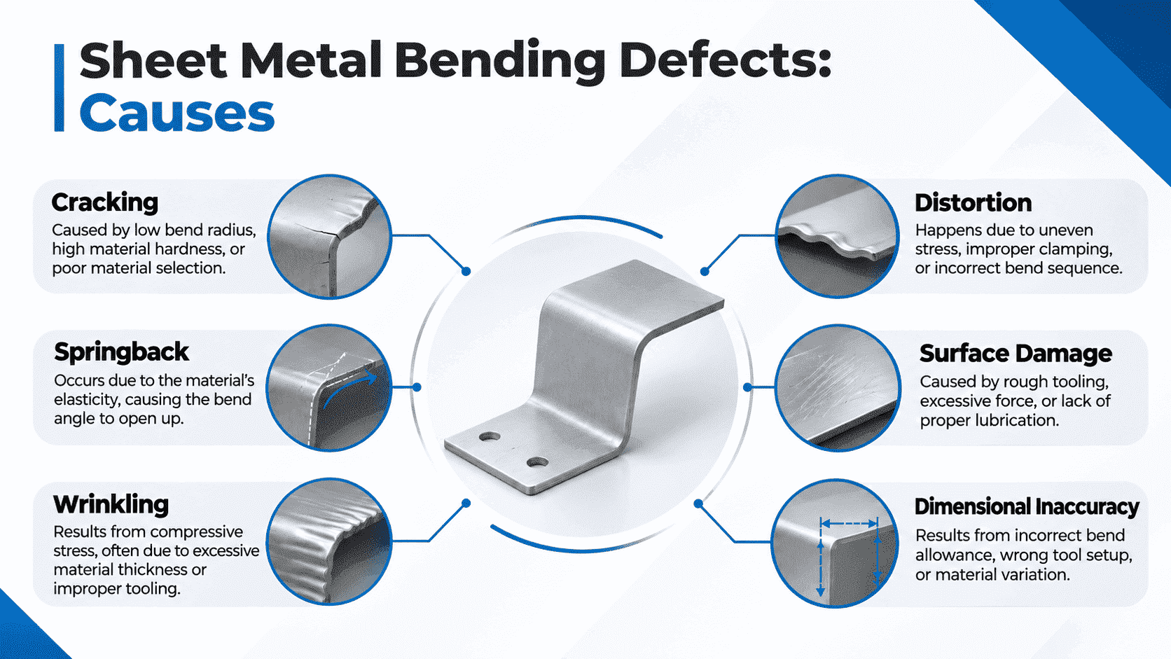
Sheet metal bending defects are flaws such as springback, bending cracks, wrinkles, angle errors and surface marks that make a bent part miss its drawing. Most of them trace back to six causes you can control: material, bend radius, grain direction, tooling, machine deflection and programming.
This guide shows you how to spot each defect, find its root cause and fix it. You will get a diagnosis table, typical springback and bend radius values, a step-by-step troubleshooting sequence and answers to the questions fabricators ask most. If your shop runs a CNC bending machine, you can apply every fix below on the press brake today.
Quick answer: Fix springback by overbending and narrowing the V-die. Fix bending cracks by increasing the inside radius and bending across the grain. Fix uneven angles by adjusting crowning and checking ram parallelism.
Sheet Metal Bending Defects at a Glance
Use this table to match what you see on the part to its most likely cause. Each defect has its own section further down.
| Defect | What you see | Most likely cause | First fix |
|---|---|---|---|
| Springback | The angle opens after the punch releases | Elastic recovery, high yield strength, wide V-die | Overbend and re-measure |
| Bending cracks | A fracture on the outer bend surface | Radius too small, bend parallel to the grain, hard temper | Increase the radius and rotate the blank 90 degrees |
| Uneven angle along the bend | The middle opens while the ends close | Ram and bed deflection, too little crowning | Adjust crowning and check tool heights |
| Left-to-right angle difference | One end bends more than the other | Unsynchronized Y1 and Y2 axes, skewed blank | Recheck synchronization and square the blank |
| Wrong flange length | Dimensions drift across a batch | Back gauge error, wrong bend deduction, blank slip | Recalibrate the gauge and verify the deduction |
| Wrinkling | Waves on the inner radius or flange | Compressive stress, thin sheet, short flange | Use a narrower V-die and add bend relief |
| Hole deformation | Oval holes near the bend | Holes too close to the bend line | Move holes or punch them after bending |
| Surface marks | Scratches, die lines or galling | Dirty or rough tooling, high friction at the die shoulder | Polish tools and use protective inserts |
Springback in Sheet Metal Bending: Causes and Compensation
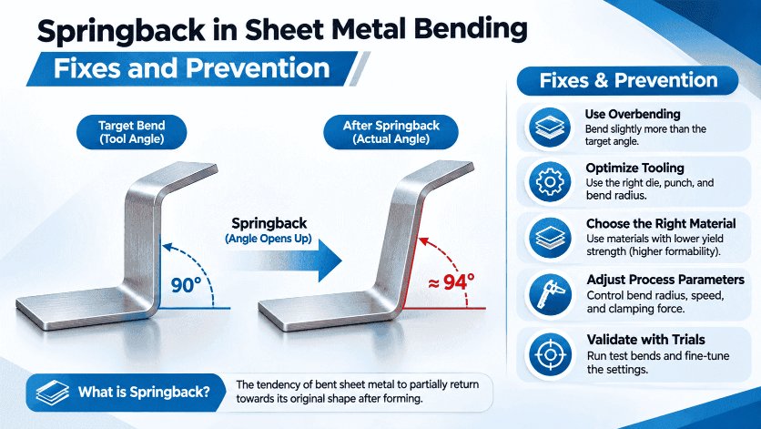
Springback is the elastic recovery that opens a bend angle after the punch releases the sheet. Every bend combines plastic deformation, which stays, and elastic deformation, which relaxes. The elastic share decides how far the angle opens.
What Increases Springback
| Factor | Effect on springback | What to do |
|---|---|---|
| Higher yield strength | More springback | Measure each material lot and adjust the program |
| Larger inside radius compared with thickness | More springback | Keep the radius close to the thickness when the design allows |
| Wider V-die opening | More springback | Narrow the V-die within tonnage and flange limits |
| Air bending | More springback than bottoming | Switch to bottoming when tolerances are tight |
| Thickness variation inside a coil | Inconsistent angles | Sort blanks or sample more often |
| Worn punch or die | Angle drift over a shift | Inspect tool radii on a fixed schedule |
Typical Springback Values
Use these ranges as a starting point for the first test bend. They fit a 90-degree air bend with a tight radius. Larger radii spring back much more.
| Material | Typical springback | Note |
|---|---|---|
| Mild steel (Q235, SPCC) | 1 to 3 degrees | The baseline for most shops |
| Aluminum 5052 | 2 to 5 degrees | Varies strongly with temper |
| Stainless steel 304 | 3 to 6 degrees | Work hardening adds recovery |
| High-strength low-alloy steel | 4 to 8 degrees or more | Check the mill certificate for yield strength |
| Soft copper and brass | 1 to 3 degrees | Low yield strength keeps recovery small |
How to Compensate for Springback
- Overbend the part. Program the target angle plus the expected springback. Bend a test piece, measure it and adjust in 0.5-degree steps.
- Narrow the V-die. A smaller opening forces more plastic deformation and cuts the elastic share.
- Switch to bottoming. Bottoming presses the sheet into the die angle and reduces springback. It needs more tonnage than air bending.
- Avoid over-coining. Excess pressure can cause springforward, where the angle closes past the die angle.
- Use CNC angle correction. A modern CNC controller stores overbend values per material. Controllers such as DELEM and CYBELEC let operators save corrections and recall them on repeat jobs.
- Control the material source. Buy from one supplier and request mill certificates. A new coil with a different yield strength changes the angle.
Servo-driven machines such as the All-electric Servo CNC bending machine help you hold a corrected depth repeatably from bend to bend.
Bending Cracks: Why They Form and How to Prevent Them
Bending cracks form on the outer surface of the bend, where tensile strain exceeds the ductility of the material. The inside of the bend compresses while the outside stretches. When the stretch goes too far, the metal fractures.
Main Causes of Bending Cracks
- Radius too small. A tight inside radius raises strain on the outer fibers. This is the most common cause.
- Bend line parallel to the grain. Rolling aligns the grain. A bend that runs along it opens cracks at lower strain.
- Hard temper or low elongation. High-strength grades and hard aluminum tempers tolerate less stretch.
- Burr on the outside of the bend. A burr or sharp cut edge starts a crack.
- Hardened cut edges. Thermal cutting can harden the edge zone and reduce local ductility.
- Surface scratches. A deep scratch across the bend line concentrates stress.
Minimum Bend Radius Chart
The table shows typical minimum inside radii as a multiple of thickness (T). Bending along the grain raises the minimum. Confirm the final value with your material supplier, because temper changes the result.
| Material | Bend across the grain | Bend along the grain |
|---|---|---|
| Mild steel (Q235, SPCC) | 0.5T to 1T | 1T to 1.5T |
| Stainless steel 304, annealed | 1T | 1.5T to 2T |
| Aluminum 5052-H32 | 1T | 1.5T to 2T |
| Aluminum 6061-T6 | 2T to 3T | 3T to 4T |
| High-strength low-alloy steel | 1.5T to 2T | 2T to 3T |
| Soft copper | 0.5T | 1T |
Example: A 3 mm mild steel sheet bent across the grain needs an inside radius of at least 1.5 to 3 mm.
How to Read the Grain Direction
Mills roll sheet in one direction. Fine lines on the surface often run along that direction, and the mill certificate or sheet label usually marks it. Orient the bend line at 90 degrees to the rolling direction. When a part has bends in two directions, rotate the blank 45 degrees so neither bend runs parallel to the grain.
How to Prevent Bending Cracks
- Calculate the radius-to-thickness ratio. Compare it with the chart above before you cut the blank.
- Mark the grain on the nest. Tell your programmer to orient the bend lines across the rolling direction.
- Put the burr on the inside. Place the burr side of the blank on the inside of the bend.
- Improve the cut edge. A clean edge from a fiber laser cutting machine or a hydraulic guillotine shearing machine resists cracking better than a rough or hardened edge. Our sheet metal cutting guide explains thickness capacity, and the laser machine maintenance guide shows how to keep cut quality stable.
- Widen the V-die and punch radius. A larger punch radius spreads the strain over more material.
- Choose a softer temper. Annealed or more ductile grades bend tighter without fracture.
Reject cracked bends on load-bearing parts. A hairline crack can grow in service. For thick plate, a large-tonnage electro-hydraulic servo CNC bending machine gives you the capacity to use a wider die and a larger radius without overloading the machine.
Angle Variation and Dimension Errors on the Press Brake
When the angle changes along one bend, the cause usually sits in the machine, not the material. Under load, the ram and bed flex. The center of the beam deflects more than the ends, so the middle of the bend opens.
| Symptom | Probable machine cause | Check first |
|---|---|---|
| The angle is larger in the middle | Too little crowning | Crowning value against tonnage and bend length |
| One end differs from the other | Y1 and Y2 axes out of sync, or uneven tool height | Ram parallelism and tool seating |
| Flange length drifts across a batch | Worn back gauge fingers or sheet slip | Gauge calibration and blank edge quality |
| The angle drifts during a shift | Tool wear, oil temperature or a new material lot | Sample the first and every tenth part |
Fix Angle Variation Along the Bend
- Adjust crowning. Add crowning until the center angle matches the ends. Record the value for each material and length.
- Check tool height and seating. Uneven punch or die heights change the angle at one end.
- Replace worn tooling. Worn shoulders and punch tips change the angle faster than most operators expect.
- Use a machine built for the job. A Torsion Shaft CNC bending machine uses a mechanical link between the ram ends to help keep them level. Your CNC controller, whether ESA or Syntec, then handles depth, crowning and angle values.
Fix Flange Length and Bend Position Errors
- Calibrate the back gauge. Reference the fingers against a gauge block at the start of each shift.
- Verify the bend deduction. Bend a test piece, measure the flange and update the deduction in your CNC program. The material and die opening both change it.
- Inspect the blank. A blank that is out of square or has a wavy edge shifts the bend line.
- Support the sheet. Large or heavy sheets sag and slip as they rise. A bending machine with follow-up material support supports the sheet as it rises and helps keep the bend position stable.
Wrinkling, Distortion and Hole Deformation
These defects come from compressive stress on the inside of the bend and from material that has nowhere to go. Design choices cause most of them, so fix the drawing as well as the process.
- Wrinkling. Thin sheet and short flanges buckle on the inner radius. Use a narrower V-die, apply pressure steadily and add a bend relief at the flange ends.
- Short flanges that twist or slip. A flange shorter than about 0.7 times the V-die opening cannot sit on the die shoulders. Lengthen the flange or choose a narrower die.
- Oval or stretched holes. A hole too close to the bend line stretches with the metal. A common design rule keeps the hole edge at least 2.5 times the thickness plus the bend radius from the bend line. Otherwise, punch the hole after bending.
- Bulging at the bend ends. Displaced material pushes outward at the edges. Add a relief notch at least as wide as the thickness and slightly deeper than the bend radius.
- Warped or twisted parts. Residual stress from cutting and uneven bends distorts the part. Flatten the blank if needed and bend symmetric features in a balanced order.
Surface Marks, Burrs and Orange Peel
Surface defects rarely affect strength, but they cause rejections on visible parts such as enclosures, panels and stainless fittings.
- Die marks and scratches. Friction at the V-die shoulders drags the sheet. Polish the shoulders, use a die with larger shoulder radii and add urethane film or nylon inserts for finished surfaces.
- Galling on aluminum and stainless steel. Material transfers to the tool and scores the next part. Use nitrided or coated tooling and keep it clean.
- Dents from debris. A chip or burr trapped between the sheet and the tool leaves a mark. Wipe the tools and blank before each batch.
- Orange peel. A rough, dimpled outer surface appears on coarse-grain material or very tight bends. Choose a finer-grain grade or increase the radius.
- Burr-side damage. Burrs scratch tools and start cracks. Deburr the blank, or place the burr side inside the bend.
Tooling and Press Brake Features That Prevent Bending Defects
Good process control still fails on a machine that cannot hold angle and position. Match the press brake and tooling to the defects you see most.
| Defect to prevent | Feature to look for | Why it helps |
|---|---|---|
| Springback and angle drift | CNC controller with programmable overbend and stored corrections | Operators recall proven values for each material |
| Angle open in the middle | Crowning (deflection compensation) | Offsets ram and bed flex along the bend |
| Left-to-right angle difference | Synchronized Y1 and Y2 axes | Keeps the ram level through the stroke |
| Wrong flange length | Multi-axis back gauge with calibration routine | Holds the bend position across the batch |
| Distortion on large sheets | Follow-up material support | Supports the sheet as it rises |
| Surface marks | Polished or hardened tools, urethane film, nylon inserts | Reduces friction and contact marks |
Which Xinli Machine Fits Which Problem
Xinli Machinery builds a full range of CNC bending machines. Ask our engineers which crowning and controller options suit your material and bed length.
- Precision and repeatability: Compare the Electro-hydraulic Servo CNC bending machine and the All-electric Servo CNC bending machine.
- Long beds and large parts: Review the Three cylinder CNC bending machine and the Large Hybrid CNC bending machine.
- Heavy plate: Check the Large-tonnage electro-hydraulic servo CNC bending machine.
- Controller choice: Choose from DELEM, CYBELEC, ESA or Syntec CNC systems.
Troubleshooting Sheet Metal Bending Defects Step by Step
Follow this order. It checks the cheapest and most common causes first, and it changes one variable at a time so you know what worked.
- Confirm the material. Check the grade, temper, thickness and rolling direction against the drawing and the mill certificate.
- Check the design. Compare the inside radius with the thickness, the flange length with the V-die opening and the hole distance with the bend line.
- Check the tooling. Pick a V-die opening of about 6 to 8 times the thickness for common mild steel sheet. Inspect the punch tip and die shoulders for wear.
- Check the machine. Verify crowning, Y1 and Y2 synchronization and back gauge calibration.
- Run a test bend. Use an offcut from the same lot. Measure the angle with a protractor or digital angle gauge.
- Adjust one variable. Change the overbend, crowning or depth, bend again and record the result.
- Inspect the first article. Measure angle, flange length and surface finish before you release the batch.
- Sample during the run. Check the first part after every tool change and one part in every ten after that.
Pre-Bend Checklist
- Material grade and temper match the drawing
- Bend lines run across the grain
- Inside radius meets the minimum for the material
- Burr side faces the inside of the bend
- Tools are clean, polished and free of wear
- Crowning and back gauge match the saved program
- A test bend on a same-lot offcut passes inspection
FAQs About Sheet Metal Bending Defects
What are the most common sheet metal bending defects?
The most common sheet metal bending defects are springback, bending cracks, uneven bend angles, wrong flange lengths, wrinkling, hole deformation and surface marks. Springback and cracks cause the most scrap. Most defects come from the material, bend radius, grain direction, tooling or machine deflection.
What causes springback in sheet metal bending?
Springback happens because bending creates both plastic and elastic deformation. When the punch releases, the elastic part relaxes and opens the angle. High yield strength, a large inside radius and a wide V-die opening increase it. Air bending produces more springback than bottoming.
How do you compensate for springback on a press brake?
Overbend the part by the expected springback, then measure and adjust in 0.5-degree steps. You can also narrow the V-die, switch to bottoming or use CNC angle correction. Save the final values for each material and thickness so operators can repeat them.
Why does sheet metal crack when you bend it?
Sheet metal cracks because tensile strain on the outer surface exceeds the ductility of the material. The usual causes are a radius that is too small, a bend line parallel to the grain, a hard temper and burrs on the outside of the bend. Increase the radius and bend across the grain.
What is the minimum bend radius for sheet metal?
The minimum bend radius is the tightest inside radius a sheet can take without cracking. Bending across the grain, it is about 0.5T to 1T for mild steel, 1T for annealed 304 stainless steel and 2T to 3T for 6061-T6 aluminum, where T is the thickness. Bending along the grain raises these values.
Does grain direction affect bending cracks?
Yes. Rolling aligns the grain, and a bend line parallel to it cracks at lower strain. Bend at 90 degrees to the rolling direction whenever possible. If a part has bends in two directions, rotate the blank 45 degrees so neither bend runs along the grain.
Why does the bend angle change along the length of the part?
The ram and bed deflect under load, so the middle of the bend opens more than the ends. Crowning offsets this deflection. Worn or unevenly seated tooling and unsynchronized Y1 and Y2 axes also change the angle along the bend.
How do you stop wrinkles and distorted holes near a bend?
Use a narrower V-die, add bend relief at the flange ends and keep flanges longer than about 0.7 times the V-die opening. Keep holes at least 2.5 times the thickness plus the bend radius from the bend line, or punch them after bending.
How do you troubleshoot sheet metal bending defects step by step?
Check the material first, then the design, tooling and machine. Run a test bend on an offcut from the same lot and change one variable at a time. Record each result, inspect the first article and sample parts during the run.
Conclusion
Sheet metal bending defects follow clear patterns. Springback comes from elastic recovery, bending cracks come from excess strain and angle errors come from machine deflection. When you check the material, design, tooling and machine in that order, you find the cause in a few test bends instead of a full batch of scrap.
Start with the diagnosis table, apply the matching fix and record the values that work. If your press brake cannot hold angle or position, explore Xinli’s range of CNC bending machines or browse our factory cases. To discuss your material, thickness and tolerance, contact our team for a quote.