Press brake bending stainless steel requires a job-specific plan for the exact grade, thickness, surface, bend geometry, tooling, and machine. Stainless sheet can respond differently from the material used to qualify a standard mild-steel setup. A familiar program, tool set, or bend allowance should not be copied without checking the material documents and the approved process chart. This guide gives a practical sequence for planning and checking stainless bends while keeping machine-specific limits with the manufacturer’s instructions.
Use the released drawing and material certificate as the source of job requirements. Stainless grades and finishes are not interchangeable, and a general guide cannot specify a safe tool or press force for an unknown sheet. Have a trained operator and responsible engineer approve the setup, especially for tight radii, high-strength grades, long bends, or close tolerances.
Press brake bending stainless steel starts with material identification
Confirm the exact alloy designation, product form, temper or condition when stated, thickness, and finish. Common stainless families such as austenitic and ferritic grades differ in composition and forming response, and nominal labels alone do not define every lot’s mechanical properties. Check the purchase specification or certificate rather than treating all material sold as “stainless” as one category.
Measure or verify actual thickness within the supplier’s tolerance and record the batch or heat identification when the job requires traceability. Thickness affects the bend geometry, required force, angle response, and flat-pattern development. A control program built for one thickness should be validated again if the stock changes or the incoming sheet falls outside the qualified range.
Record any grain-direction requirement, protective film, brushed or mirror finish, and visible-side callout. The drawing may specify a bend direction relative to grain or require the cosmetic face to stay free of scratches. These details affect blank orientation, handling, support, tooling cleanliness, and inspection. If the print does not define the acceptable surface condition, get that requirement clarified before production.
Review the bend geometry and acceptance criteria
For every bend, list the line length, included angle, inside radius, flange dimensions, nearby holes or cutouts, and tolerance. Identify which dimension is the primary acceptance feature: angle, flange length, radius, flatness, or a relationship between bends. A part may meet an angle target and still fail its radius or finished dimensions, so the inspection plan should cover all called-out requirements.
Check whether the drawing’s radius refers to the finished inside radius, an outside dimension, or a tool nose. These terms describe different measurements. Air bending forms a radius influenced by the die opening, material, thickness, and process conditions; a punch nose does not automatically equal the finished inside radius. If the radius is tight or critical, use the validated data for the exact grade and tool set.
Inspect the entire part for features that can interfere with bending: holes near the bend line, slots, welds, hems, return legs, formed extrusions, and surfaces that must not be marked. Check the bend sequence as well as each isolated bend. A stainless part that clears the tools in its flat state can still collide after an earlier wall has been formed.
Check the cut edge and its condition before forming, especially where the bend line crosses a sheared or laser-cut edge. Burrs, notches, and rough edges can affect appearance and may contribute to a crack or measurement issue. Follow the drawing and shop standard for edge preparation; do not grind away material or introduce contamination without an approved method. Keep the edge orientation consistent with the qualified bend setup.
Use stainless-specific tooling and force data
Choose the punch and die from a current chart that covers the actual stainless grade or an explicitly approved material family, thickness, radius, angle, and process. Do not assume a mild-steel V-opening or force chart is a valid stainless setting. Manufacturers often provide separate columns or tables for material type; use the table’s units, stated strength assumptions, and warnings.
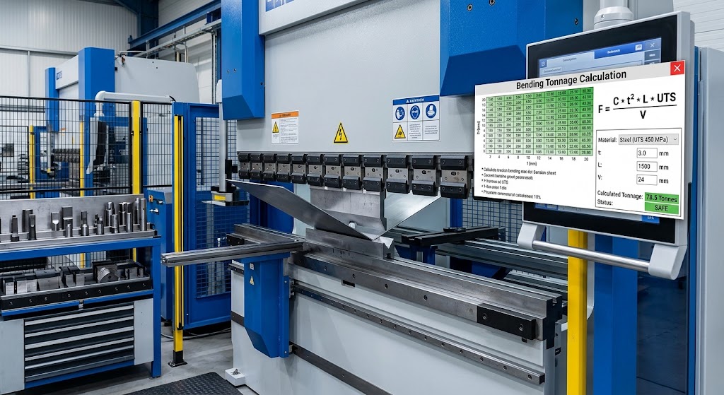
Calculate or retrieve the required force for the bend length, thickness, material strength, die opening, and forming method. Then check the press brake’s working-length and loading restrictions, including local or off-center limits, and verify the ratings of the punch, die, clamp, holder, and segments. The setup is limited by the lowest applicable rating. A high-capacity machine does not raise the rating of a tool or clamp.
Stainless jobs can demand more force than an otherwise similar mild-steel job, but the amount depends on grade, condition, geometry, and the chart’s assumptions. Do not apply a generic multiplier unless the approved calculation method specifies it. If the grade or strength value is missing, get the information from the material supplier or engineering before selecting a program or trial setting.
For the general tool-selection workflow, see how to select press brake tooling for a job. Use the minimum flange length guide if the part has a short leg, and the tonnage calculation guide for the force calculation concepts. These related guides do not replace the stainless-specific maker chart for the job.
Choose a bend radius that matches the grade
Review the specified inside radius against the material manufacturer’s forming guidance and the available punch and die geometry. A very tight radius can concentrate strain at the bend and increase the risk of cracking, especially if the material, surface, grain direction, or tooling is outside the qualified conditions. Do not reduce the radius simply because a tool is physically available.
Check the bending direction and material orientation if the process specification identifies a preferred direction. The sheet surface, grain direction, edge quality, and cut condition may affect the finished bend. If cracks or edge tears appear during a trial, stop and investigate the material certificate, blank edge, radius, bend direction, tool condition, and program instead of continuing to produce parts.
A change in die opening can alter the resulting radius and required force. If the radius does not meet the drawing, do not make an unrecorded tool substitution or arbitrary angle change. Ask engineering to evaluate the dimensions and tool chart, then inspect the first piece against both the radius and angle requirements. Read the dedicated sheet-metal bend-radius guide for the calculation variables and limits.
Account for springback and angle consistency
After forming, stainless material can spring back, leaving an angle more open than the angle under load. The amount varies with alloy, thickness, radius, bend length, and process conditions. A control may measure or compensate for angle, but its material library, calibration, and setup procedure must match the machine and actual grade.
Start with the qualified program or approved chart, then make a controlled first piece. Measure the released angle using the specified gauge and location. If it is outside tolerance, follow the approved adjustment procedure and record the change. Do not copy an overbend setting from a different grade or batch based only on the nominal thickness.
For tight angle tolerances, inspect the part at the defined points along the bend, including both ends where the plan requires it. A long bend may show variation from machine deflection, material variation, or alignment. Confirm any crowning or angle-compensation setting from the approved procedure rather than using a generic correction. See the springback compensation guide for the general variables behind that topic.
Protect stainless surface finish during setup
Keep the tool faces, supports, and work surface clean before loading a cosmetic stainless part. Embedded chips, burrs, dirt, or residues can scratch or imprint the sheet as it moves across the die shoulders. Use an approved protective film, urethane, foil, or marking-prevention accessory only when the process allows it and the selected material and tooling are compatible.
Use clean gloves and handling surfaces when the customer or shop specification calls for contamination control. Keep stainless blanks separated from carbon-steel swarf, dusty racks, and dirty handling equipment. Any contamination-control requirement should come from the customer specification, quality procedure, or material supplier; do not claim that a generic precaution guarantees corrosion performance.
Inspect both the visible face and bend area for scratches, drag marks, dents, embedded particles, and unintended tool impressions. Check whether the die shoulder finish and radius are appropriate for the surface requirement. If a marking-protection product changes friction, placement, or angle, include it in the qualified setup rather than adding it casually after the process has been approved.
Plan blank development and bend sequence
Use a material- and tooling-specific bend allowance or bend deduction table for stainless stock. Flat-pattern dimensions depend on material behavior, thickness, inside radius, die geometry, bend angle, and the method used to develop the blank. A mild-steel deduction may not produce the required finished dimensions in stainless. AMADA’s tooling reference, for example, presents bend-allowance values separately for mild steel, stainless steel, and aluminum under its chart conditions.
Confirm the flat pattern and bend deductions with the responsible design or programming workflow. If the part has multiple bends, check how errors accumulate across the finished dimensions and whether the bend sequence changes the gauging face. Do not change a released CAD value on the machine. Route any mismatch between the sample and drawing through the approved engineering change or process correction.
Build the sequence so the part remains accessible and can be supported without dragging the cosmetic face across dirty tooling. Check whether previously formed legs block the punch, backgauge, or operator’s hold. If the part cannot be safely rotated or supported, review a different sequence or an approved support fixture before making the first piece.
Set up the backgauge and part support
Choose a consistent datum on the drawing for the backgauge and confirm that the edge used for positioning is straight, clean, and free of burrs. Thin or flexible flanges may need an approved support method to avoid sagging or rocking against the gauge. Confirm fingers, stops, or fixtures do not contact holes, returns, or the finished surface in a way that shifts the part.
Verify the programmed backgauge position and actual machine setup against the bend sequence. A small positioning error can change flange length or cause a feature to approach the bend line. For parts with several bends, record the datum and orientation at each operation so operators do not flip the part differently between pieces.
Long or heavy sheets may require a lifting aid or support device. Plan how the operator will load, rotate, and remove the material while keeping clear of pinch and crush zones. Follow the machine manual, guarding, and shop safe-work rules. Never trade safety or stable handling for a faster cycle or a marginally fitting flange.
Run a controlled stainless first-piece trial
Before production, compare the material label and certificate with the setup sheet. Confirm the grade, thickness, finish, and orientation; inspect the tools for damage and contamination; verify the machine and tooling ratings; and check the program’s tool definitions. Use the prescribed setup and safety procedures for the press brake. Do not use an unqualified piece of a different alloy as proof for the production batch.
Make the first part under the approved process and inspect the required dimensions. Check angle, radius, flange lengths, overall size, twist, cracks, edge condition, and surface finish as relevant to the drawing. Use calibrated gauges identified by the inspection plan. Record the batch, tool IDs, program revision, machine, actual measurements, and authorized adjustments.
If the bend is out of tolerance, stop and identify whether the cause is the material, thickness, blank development, tool geometry, machine setup, measurement method, or program. Change only one approved variable at a time where the procedure requires it, then make and inspect a new first piece. Do not compensate for a bad radius by changing only the angle if that could conceal a geometry or tooling problem.
Common stainless bending mistakes
- Using mild-steel settings unchanged: confirm that material-specific data and calculations match the stainless grade.
- Assuming all stainless grades behave alike: use the certificate and approved grade-specific limits.
- Copying a bend deduction: confirm the flat-pattern method and table are valid for the material and tooling.
- Ignoring grain, finish, or the visible face: orientation and surface requirements belong in the setup notes and inspection.
- Making a radius tighter without review: check material guidance and tooling limits before revising the bend.
- Using a generic springback correction: validate the control, calibration, and first-piece result for the actual batch.
- Adding a protector after approval: friction or thickness can change the process; qualify permitted accessories in advance.
Press brake stainless setup checklist
- Verify alloy designation, condition, thickness, batch, finish, and any grain-direction requirement.
- Confirm each bend’s angle, radius, flange, tolerance, inspection datum, and visible surface.
- Select punch, die, method, force, and program from applicable stainless-specific data.
- Check machine, tool, clamp, segment, and off-center load limits.
- Confirm bend sequence, backgauge datum, part clearance, handling, support, and surface protection.
- Use the released flat pattern and material-specific bend allowance or deduction data.
- Inspect and record the first piece before production and revalidate after material or setup changes.
Frequently asked questions
Can I use a mild-steel press-brake program for stainless steel?
Only if the responsible engineering process has validated it for the exact stainless grade, thickness, tooling, and machine. Material-specific force, angle, radius, and bend-development data may differ. A similar thickness alone is not sufficient validation.
Does stainless steel always need a larger bend radius?
There is no single radius for every stainless grade and thickness. Use the material supplier’s forming guidance and the toolmaker’s chart for the specified bend direction, geometry, and finish. Validate a critical radius with the approved process.
Why does my stainless angle change between batches?
Grade, condition, thickness, strength variation, tooling, setup, and measurement can all affect the result. Compare the new certificate and actual thickness with the qualified job range, then follow the approved first-piece procedure.
How do I protect a brushed or polished stainless surface?
Follow the customer’s finish requirements and shop procedure. Keep tools and supports clean, handle parts carefully, and use only approved surface protection that has been validated with the bending process.
What if the stainless bend cracks?
Stop the operation and isolate affected parts. Review the grade and certificate, edge condition, bend direction, radius, tool geometry, and setup with engineering or the material supplier. Do not keep running parts while the cause is unknown.
Related resources and source note
For tooling selection see how to select press brake tooling for a job, and for bend allowance see bend allowance and bend deduction calculation. Browse Xinli’s press brake and bending machine range, or contact Xinli Machinery with the drawing and material certificate if application review is needed.
Manufacturer references: the AMADA tooling reference presents different bend-allowance tables for mild steel, stainless steel, and aluminum under its stated conditions. TRUMPF’s bending-process overview explains how tools and material properties affect the path and force. Check current manufacturer manuals and Xinli’s approved application data for the exact machine before production. Before publication, have Xinli’s technical team review the stainless-specific claims and add an approved shop example or inspection photo.