Minimum flange length for press brake bending is set by the geometry of the selected punch and die, the material, the bend method, and how the drawing defines the dimension. A flange that looks long enough on a part sketch may not sit securely on the die shoulders or may collide with the punch as the sheet rotates. The right check is therefore made against the exact tooling chart and the actual job dimensions, not a single ratio copied between machines.
This guide explains how to identify the controlling flange dimension, use manufacturer charts, test a candidate die opening, and respond when a design falls below the recommended minimum. A few suppliers publish useful screening values, but they are examples for defined tool and process conditions. Always use current data for the machine and tools in your shop.
Minimum flange length for press brake bending: what the value means
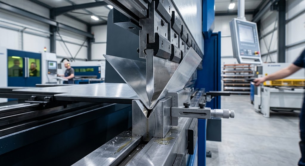
The minimum flange is the shortest leg that a specified tooling setup can form while keeping the sheet supported and the bend repeatable. For a standard air-bending V die, the outside leg usually has to reach the die shoulder area in a way that allows the workpiece to rotate as the bend is made. If the flange is too short for the opening and process, it may slip, tip, deform unexpectedly, or produce an inaccurate angle.
The term can refer to an inside or outside flange dimension depending on the chart and calculation method. Drawings also vary: a dimension may be to the theoretical intersection, to a tangent point, or to an edge after a radius is formed. Do not compare a drawing’s inside leg directly with a chart’s outside dimension without converting it using the specified bend radius and datum. Ask engineering to clarify an ambiguous print before setup.
Minimum flange is a tooling-fit limit, not the same as the preferred flange for a stable part or a design guideline for holes near bends. A part can exceed the tooling minimum and still be difficult to gauge, support, or inspect. Conversely, a design may be formable with a special process even when it is below the common minimum for standard V tooling. Keep design limits, process limits, and safety checks separate.
Start with the released drawing and material
Record the drawing revision, material grade and condition, thickness, bend angle, specified inside radius, bend length, finish, and tolerance. Note whether the flange dimension is measured from the outer edge or the inside face. Check whether holes, slots, cutouts, welds, embossments, coatings, or preformed features sit close to the bend line. These details can change the usable contact area or create interference.
List the flange on every bend in the sequence rather than checking only the first bend. A part may start as a flat blank with a long edge, then acquire a wall that constrains how the next short leg can be formed. Record the height and direction of previously formed legs because they may collide with the punch, ram, backgauge, or operator support even when the nominal flange length meets the die chart.
Use the maker’s chart before applying a shortcut
The most reliable starting point is a current chart from the press-brake or tooling manufacturer for the exact die family, material, thickness, bend type, and dimensional convention. Some charts report minimum flange alongside die width, bend radius, and force. Use those linked values together; a flange number taken out of a chart may not remain valid when the die opening, tool angle, material, or process changes.
Bystronic’s published selection guidance gives an approximate screening relationship of about 77 percent of the V opening for the minimum flange in its described V-die context. It illustrates that a 1-inch opening needs roughly a 0.77-inch flange, and discusses selecting a narrower die for a shorter leg. This is an example from that manufacturer’s guidance, not a universal acceptance criterion for every brand, material, die profile, or machine.
Other makers publish their own tables and calculations. AMADA’s air-bending chart, for example, lists minimum flange length alongside die opening for specified chart conditions. TRUMPF’s tool manual contains a separate minimum-flange calculation section, and its catalogs can provide tool-family-specific data. Use the applicable table, units, and stated assumptions rather than combining one company’s flange ratio with another company’s force chart.
How to screen a flange against a V-die opening
Write down the candidate V opening and the chart’s minimum flange for that opening and material condition. Compare that value with the drawing’s corresponding dimension after confirming that both are measured in the same way. If a chart offers a range or multiple cases, choose only the row that matches the actual thickness, bend angle, tool geometry, and material category.
As a screening example only, if a supplier’s guidance gives a 0.77-inch minimum for a particular 1-inch die context and a print calls for a 0.50-inch leg, the standard opening appears too large for that short flange under that guidance. The result does not prove that every 0.625-inch die is suitable; the alternate opening must be checked for radius, material, load, accuracy, and tool rating. The example shows how the comparison works, not a universal recipe.
Why die opening changes the minimum flange
The die shoulders support the sheet while the punch drives the center of the bend downward. A wider opening places the shoulders farther apart, so the edge of a short flange may not reach a stable contact area. A narrower opening can bring support closer to the bend and may permit a shorter leg in some applications, but it also changes the forming geometry and force demand.
Changing the opening can affect the resulting inside radius, bend force, angle behavior, marking, and the distance the sheet needs to travel. A die that solves flange reach may create a radius outside the print, increase force, or reduce angular accuracy. Review the separate V-die opening guide and bend-radius guide for those dedicated decisions; do not treat the minimum flange calculation as a substitute for them.
There are practical limits to narrowing a V die. Bystronic notes that a die width below a multiple of the material thickness can create accuracy problems and risks to the tooling, machine, and operator. The relevant threshold depends on the supplier’s design and data. Do not use a smaller opening just because it gives a minimum-flange number that looks closer to the print.
Check punch geometry and the bend method
The upper tool can affect whether a short leg clears the punch body during forming. Check punch nose angle, radius, height, profile, and any relief or gooseneck shape against the part and its bend sequence. A straight punch may collide with a return leg while a relieved punch creates clearance, but it must still meet the capacity, clamp, and process requirements. Use a dimensioned profile drawing or approved simulation to check the full part path.
Air bending, bottoming, coining, hemming, and special forming operations have different contact conditions. A minimum determined for air bending should not be applied to a hem pre-bend or bottoming operation unless the applicable chart says so. Bystronic’s guidance, for example, identifies a larger suggested flange ratio for a 30-degree hem pre-bend than for its standard V-die case. Use the process-specific value and confirm the exact tool combination.
Where a bend method is not stated on the process sheet, resolve that decision with engineering. Changing the process to make a short leg fit can substantially change load, radius, angle control, and tooling stress. See the air bending, bottoming, and coining comparison for the high-level process differences before selecting a validated job-specific method.
Include the whole sequence and part handling
Evaluate each bend as a three-dimensional part state. A narrow flange might be formed first while the sheet is flat, but a later short flange may be trapped by a taller wall. Confirm which face contacts the die and how the part will be turned, located, and removed. The minimum on a chart does not account for every possible collision with the machine or adjacent features.
Check that the operator can support the workpiece safely and consistently. A small flange may be difficult to hold against a backgauge or may shift as the bend starts. Long or asymmetric parts can require approved supports or lifting equipment. Use the machine’s guards and safe operating procedures; a setup that requires hands to enter a hazard area to hold a short edge is not acceptable.
For complex boxes, channels, returns, and parts with preformed legs, compare the tool and part drawings in a bend simulator or other approved planning method. Include the actual tool height, die width, clamp, ram, backgauge, support devices, and bend sequence. If a generic tool model does not show the relief or dimensions of the actual punch, mark the clearance check as incomplete.
Short flange alternatives and design changes
If a standard die does not meet the flange requirement, first check whether the drawing allows a modest design adjustment. A longer flange may make the part easier to form, measure, and support. A revised inside radius or bend location may also create room, but only the design authority can approve a change to the released geometry. Do not alter a production drawing at the machine without the required approval.
If the geometry must remain, ask engineering or the tooling supplier to evaluate an approved narrower die, special tool, offset punch, relief, hemming tool, or alternate process. Each alternative needs its own capacity and quality review. A special tool may solve clearance while introducing setup, handling, marking, or cost considerations. Do not assume that a narrow tool is safe just because its nominal opening matches the leg.
For some parts, a different manufacturing route may be appropriate, such as changing the bend sequence, using a dedicated forming tool, or revising a design feature. Compare options based on dimensional accuracy, material, production volume, tool availability, inspection, and safe handling. The chosen method should be written into the approved process plan so a future shift does not revert to an unsuitable standard setup.
Check capacity and accuracy before trial
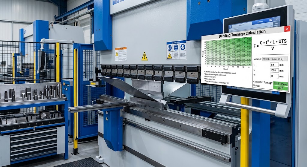
For each candidate opening, confirm force using the correct chart or approved calculator for material, thickness, bend length, and method. Separately verify machine force over the loaded length and the ratings of the punch, die, holder, clamp, and individual segments. Check off-center load restrictions and any limits on using a very narrow die. The allowable setup is controlled by the lowest applicable rating.
Review the press brake tonnage calculation guide for the calculation concepts, then use the actual maker data for the job. A force estimate that assumes mild steel or a standard die opening cannot validate an unlisted material or special setup. If input values are missing or the calculation approaches a limit, pause for engineering review instead of trying the setup by feel.
Specify how the first piece will be checked: dimension reference, angle, radius, flange length, surface condition, and inspection tool. A short flange can magnify small placement errors, so plan the gauge contact and measurement method before running the bend. Record the actual stock thickness, tool IDs, machine, settings allowed by the procedure, and results for traceability.
First-piece inspection for a short flange
Confirm that the selected tools match the approved setup sheet and that their working surfaces and locating features are clean and undamaged. Verify secure clamping and alignment using the machine instructions. Make the first piece through the approved controlled setup process, keeping clear of the danger zone and using specified handling aids.
Measure the flange at the datum shown on the drawing and inspect angle and radius against their own tolerances. Check whether both ends of a long bend match and whether the edge shows slipping, crushing, cracking, or unintended marks. Do not judge acceptance by whether the leg merely appears to reach the die. Use the customer’s drawing and inspection plan.
Common mistakes when checking minimum flange
- Applying one ratio to every tool: screening percentages are context-specific; the tool maker’s chart for the exact setup is controlling.
- Mixing inside and outside dimensions: confirm the chart’s datum and the print’s measurement before comparing values.
- Choosing a narrow die without checking radius and force: short-leg clearance does not establish that the bend is accurate or within capacity.
- Ignoring the next bend: a flange that forms first may block access to a later operation.
- Assuming a chart covers every alloy: use material-specific data and verified strength inputs.
- Rounding a borderline dimension down: tolerances and real stock variation need to be considered.
- Proceeding with a near-collision setup: tool fit must be assessed through approach, forming, rotation, and withdrawal.
Minimum flange length checklist
- Confirm drawing revision, flange dimension convention, material, thickness, bend angle, radius, and bend length.
- Identify the forming method and exact punch, die, tool system, and machine.
- Find the manufacturer’s minimum flange value for the matching chart row and units.
- Compare like dimensions and check the full bend sequence for punch, die, and machine interference.
- Verify that any alternate die still meets radius, force, accuracy, and tool ratings.
- Confirm part support, gauging, access, and safe handling requirements.
- Record the tool IDs, chart reference, first-piece measurements, and any approved adjustment.
Frequently asked questions
Is minimum flange always 77 percent of the V opening?
No. Bystronic publishes about 77 percent as an approximate value in its described V-die guidance. Other makers provide their own tables and calculations, and tool geometry, material, angle, and process affect the result. Use the chart for the actual tooling system.
Can a smaller die opening solve a short flange?
Sometimes it can improve support for a shorter edge, but the opening also affects radius, force, and angle behavior. Verify all those limits and the manufacturer’s minimum die-width restrictions before considering the change.
Can a hem use the same minimum-flange value as an air bend?
Not necessarily. A hem pre-bend uses a different angle and can have a different minimum. Use the specific chart and tool instructions for the hem operation, then verify force and clearance.
What if the print is shorter than the chart value?
Ask engineering or the tooling supplier to review a compliant alternative. Options can include a design change, different approved die, special punch, or different process. Do not make an unapproved substitution at the press brake.
Related guides and sources
For the broader punch-and-die selection workflow, see how to select press brake tooling for a job. Explore Xinli’s press brake and bending machine range, or contact Xinli Machinery with the drawing revision and material details if a short-flange application needs review.
Source references: Bystronic’s press-brake tooling guidance describes an approximate minimum-flange example and explains the tradeoffs of narrowing a die. The AMADA air-bending force chart lists minimum flange together with die opening for its chart conditions. The TRUMPF bending-tools manual includes a dedicated minimum-flange calculation section. Before publication, have Xinli’s technical team validate the method against its available tool charts and add a reviewed example for its customers.